MECHANICAL VENTILATION AND AIR HANDLING SYSTEMS
Advantages and benefits
The building industry has long understood the countless benefits of controlled mechanical ventilation (CMV) for air handling, an interesting and evolving landscape. These are no longer very simple units with fans and filters, but new-generation units that, in addition to providing air exchange, filtration, and possibly heat recovery, combine typical air-conditioning techniques (such as cooling or heating), or air renewal and dehumidification by means of a special refrigeration circuit. The latter are designed to work in conjunction with radiant systems in cooling.
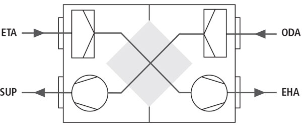
Components of residential and two-way ventilation units on the market.
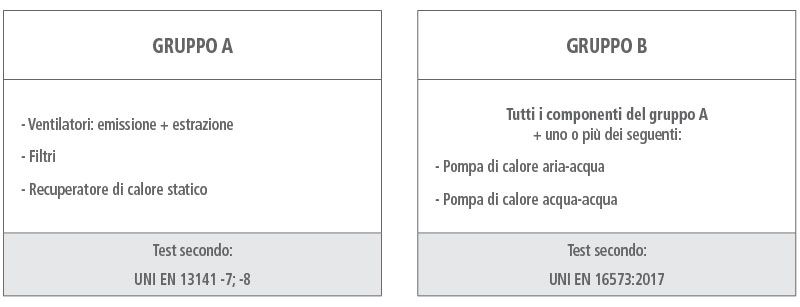
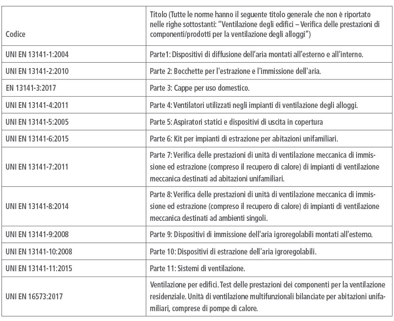
CERTIFICATION ACCORDING TO PRODUCT STANDARDS
Product standards make it possible to uniquely define the characteristics of machines and clarify how to certify the unit or components at an accredited laboratory.
GROUP CENTRAL UNITS A
The regulations implementing the ErP Directive, containing the ecodesign criteria that apply to ventilation units, are two:
“REGULATION (EU) No. 1253/2014 of July 7, 2014 implementing Directive 2009/125/EC of the European Parliament and of the Council with regard to ecodesign requirements for ventilation units,” and “DE- LEGATED REGULATION (EU) No. 1254/2014 of July 11, 2014 supplementing Directive 2010/30/EU of the European Parliament and of the Council with regard to energy consumption labelling of residential ventilation units.” Both are specific to the non-industrial sector.
Definitions taken from Regulation 1253 of 2014:
(1) ventilation unit - UV: an electrically powered unit equipped with at least one impeller, motor, and case, intended to carry out the exchange of exhaust air with air from outside in a building or part thereof
(2) residential UVR ventilation unit: a ventilation unit: (a) whose maximum flow rate does not exceed 250 m3/h; (b) whose maximum flow rate is between 250 and 1000 m3/h and intended, as declared by the manufacturer, exclusively for ventilation purposes in residential buildings
3) UVNR non-residential ventilation unit: a ventilation unit with a maximum flow rate of the ventilation unit exceeding 250 m3/h and for which, where the maximum flow rate is between 250 and 1000 m3/h, the manufacturer has not declared that it is intended exclusively for ventilation purposes in residential buildings
(4) maximum flow rate: the declared maximum air flow rate of a ventilation unit, achievable with integrated or separately supplied control devices, under normal air conditions (20°C and 101 325 Pa), provided that the unit has been installed in its entirety (e.g. is equipped with cleaning filters) and in accordance with the manufacturer's instructions [...].
5) unidirectional ventilation unit (UVU): a ventilation unit that produces airflow in one direction only, either from the inside and directed outward (ejection) or from the outside and directed inward (inflow), in which the mechanically produced airflow is balanced by natural air intake or exhaust systems
(6) bi-directional ventilation unit (UVB): a ventilation unit that produces airflow between the inside and the outside and is equipped with both outgoing and incoming fans
(7) specific energy consumption (SEC) (expressed in kWh/(m2.a)): a coefficient expressing the energy consumed to ventilate one m2 of heated living space in a dwelling or building, calculated for UVR in accordance with Annex VIII
(8) heat recovery system (HRS): part of a two-way ventilation unit equipped with a heat exchanger designed to transfer the heat contained in the exhaust (contaminated) air to the intake (fresh) air
9) thermal efficiency of a residential HRS: the ratio of the thermal gain of the supply air to the thermal loss of the exhaust air, both referred to the outdoor temperature, measured in the dry state of the HRS and under standard atmospheric conditions, with balanced mass flow, at the reference flow rate and an indoor/outdoor thermal difference of 13 K, without correction according to the thermal gain of the fan motors
10) internal leakage rate: the fraction of the exhaust air present in the inlet air of ventilation units with HRS due to leakage between the exhaust and inlet air flows inside the case when the unit is operating at the reference flow rate, measured at the ductwork
11) residual flow: the percentage of exhaust air that is reintroduced into the inlet air for a regenerative heat exchanger according to the reference flow rate;
(12) external leakage rate: the fraction of the reference flow rate that escapes from the case of a unit to the outside air, or from the outside air to the case, when it is leak tested
(13) mixture: immediate recirculation or mixing of airflows between the exhaust and inlet openings on both indoor and outdoor terminations, whereby these flows do not contribute to the effective ventilation of the enclosed space when the unit is operated at the reference flow rate
(14) mixture percentage: fraction of the exhaust airflow, forming part of the total reference flow rate, that recirculates between the exhaust and inlet openings on both indoor and outdoor terminations without contributing to the effective ventilation of the enclosed space when the unit is operated at the reference flow rate
(15) effective power input (expressed in W): electrical power input at the reference flow rate and the corresponding total external pressure difference, which includes the electrical power requirements for fans, control devices (including remote control devices), and the heat pump (if integrated)
16) specific power input (SPI) (expressed in W/(m3/h)): the ratio of the actual power input (in W) to the reference flow rate (in m3/h)
(17) reference flow rate (expressed in m3/s): the value on the x-axis of a point on a flow-pressure diagram curve that coincides with a reference point, or is at the closest possible proximity, at least 70% of the maximum flow rate and at 50 Pa for duct units and at minimum pressure for nonduct units. For bi-directional ventilation units, the reference flow rate applies at the intake air inlet
(18) environmentally controlled ventilation (DCV): a ventilation unit that makes use of environmental control.
19) ducted unit: a ventilation unit designed to ventilate one or more rooms or enclosed spaces in a building with the use of air ducts and equipped to be fitted with duct connections
20) non-ducted unit: a ventilation unit intended to ventilate only one room or enclosed space in a building and not equipped to be fitted with connections to ducts
21) recovery heat exchanger: a heat exchanger intended to transfer thermal energy from one air stream to another without the movement of elements, such as a plate or tubular heat exchanger with parallel flow, cross flow, or counterflow, or with a combination of these, or a vapor diffusion plate or tubular heat exchanger
(22) regenerative heat exchanger means a rotary heat exchanger that contains a rotating element to transfer thermal energy from one air stream to another, including material used to transfer latent heat, a drive mechanism, a case or casing, and sealing devices to reduce bypass and air leakage from one of the streams; such heat exchangers have different performance in moisture recovery depending on the material used
23) thermal bypass device: any solution that bypasses the heat exchanger or automatically or manually controls its performance in terms of heat recovery, even in the absence of a physical airflow bypass device (e.g., summer operation device, rotor speed control, airflow control).
Definition number 7 is particularly significant because it connotes the acronym and unit of measurement of the value to be included in the energy label of a ventilation unit to describe its class. It is precisely the SEC “Specific Energy Consumption” and ranges from a scale of negative values starting from -42, down to zero.
The label should contain the following information:
- The name or trademark of the supplier
- The model identifier of the unit
- The energy efficiency class (the location of which results from the SEC of the specific unit, with reference to definition 7)
- The sound power level
- The maximum flow rate (see definition 4).
The SEC is calculated by a mathematical formula that is contained in Annex VIII of Regulation 1254:2014.
TYPES OF VENTILATION SYSTEMS
In the context of situations where Residential Ventilation Units (UVRs) can be used, mechanical ventilation systems are essentially divided into two categories that have different development of aeraulic networks: unidirectional systems and bidirectional systems. For each type of system, a type of operation can be set to achieve constant or variable air renewal through appropriate sensors.
Unidirectional systems for extraction: the introduction of air into the rooms occurs through specific and certified devices installed on the window frames (box or on the frame) or on the external walls, which are crossed by a short section of duct. This system does not require a network of supply ducts.
Single-flow by supply systems: the supply air network is connected to a fan that pushes outside air into bedrooms and living rooms; in bathrooms and kitchens, overpressure air exit devices are installed. These systems are particularly used in England, but recently a single-room system, integrated with the window frame, has also been introduced in Italy, which allows air to be introduced, in this case filtered.
Bi-directional systems: it is necessary to install two aeraulic networks, one for supplying fresh air to the bedrooms and living rooms, and one for recovering stale air from bathrooms and kitchens. With this type of system it is always possible to filter the outside air according to its degree of pollution and recover part of the heat from the outgoing air to transfer it to the incoming air, without any contamination occurring between the two flows.
In general, the following aspects are evaluated when choosing a bi-directional ventilation system, in addition to economic aspects and those related to the possible encumbrances of central units and ducting:
- installation mode
- efficiency of the heat recovery unit, when present
- electrical consumption of the fans
- possibility of varying the flow rate.
ACUSTICS
All acoustic aspects of the ventilation system are regulated by laws and standards, because obviously the movement of air by mechanical fans generates noise and the problem can be significant in both ducted and ductless systems.
For bi-directional ducted units with heat exchanger, the acoustic tests to be carried out are specified in EN 13141-7.
The parameters to be measured are respectively
- the acoustic power emitted by the casing
- the acoustic power radiated in the ducts.
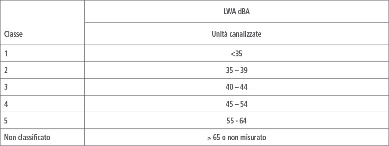
With regard to the ‘radiative sound power’, i.e. the sound power emitted by the ventilation unit casing expressed in dBA, the test report must contain the level corresponding to the so-called reference flow rate. According to the standardisers, in fact, the noise level at maximum flow rate is not particularly significant, as it is associated with a short and occasional peak trend (which the standard defines as a ‘boost’), for which a momentary overshoot of optimal conditions is tolerable.
Since ducted units - which generally move a greater flow of air than ducted units - are frequently installed in special technical spaces and can more easily be equipped with devices to reduce the noise emitted (anti-vibration joints, insulating layer in the casing, closing panels, etc.), higher levels of acoustic power have been considered acceptable compared to those emitted by single room units.
For bi-directional, ductless units with heat exchanger, the acoustic tests to be carried out are specified in EN 13141-8.
The parameters to be measured are respectively
- the acoustic power emitted in the room
- the acoustic insulation of the ventilation unit between the internal and external environment.
PREDICTING NOISE IN OPERATION
The choice of a ventilation unit should not be made solely on the basis of the value of the acoustic power emitted, as this figure only takes on full design significance when combined with the other information relating to the unit, i.e. the specific power consumption per unit flow rate, the level of filtration, the air flow rate delivered at different speeds and finally the heat recovery efficiency of the heat exchanger.
The main doubt that reigns on the subject is related to this question: starting from the acoustic power data emitted by a ventilation unit, is it possible to make a forecast assessment of the sound pressure level that any technician, equipped with a sound level meter, could subsequently verify in a room (bedroom, living room or study)?
The answer to this question is not only affirmative, but introduces another important aspect, namely that the indoor environment quality design regulations instruct the technician to establish a sound pressure level as a design objective, whereas ventilation units, as we have seen above, are certified according to the level of sound power emitted. How then?
First of all, we must not confuse sound power level and sound pressure level. This serious mistake is still made in technical documentation and design drawings. For example, nobody would ask for ‘a 20°C heater’, so nobody can simply say that an appliance ‘produces a sound pressure level of 30 dB’. Just as the temperature that is set in the room is a consequence of the power of the heater and the heat flux dispersed by the room, in the acoustic field the sound pressure that is realised in a room is a consequence of the acoustic power emitted by the source and the acoustic characteristics of the room (size and sound absorption of the surfaces and furniture).
After that, it is important to know that in order to go from the sound power level emitted by a ductless ventilation unit to the measurable sound pressure level in a given room, a mathematical procedure must be used that takes into account the dimensional aspects of the room itself and an appropriate value for its reverberation time. For the residential sector, it is standard practice to assign 0.5 seconds.
GROUP CENTRAL UNITS B
This type of compressor racks can be particularly interesting in combination with radiant heating and cooling systems as they offer some additional functions compared to group A compressor racks, such as the possibility of recirculation, pre-heating, etc.
The reference product standard for this type of power packs is very recent, it is UNI EN 16573:2017, which proposes 18 different configurations of power packs for each of which a technical reference diagram is provided.
EN 16573 describes how to perform tests for the following characteristics and performance:
- Aerodynamic characteristics
- Thermal characteristics (covering situations with and without recirculation, a condition not considered in the product standards of EN 13141)
- Performance of the static heat exchanger
- Performance of the ventilation system whose exhaust air heat is used for domestic hot water production by means of an air-water heat pump
- Performance of the ventilation system with hydronic heating/cooling
- Performance of ventilation system with hydronic heating/cooling of incoming air
- Performance of ventilation system with possibility of domestic hot water production combined with hydronic heating/cooling of incoming air
- Performance of ventilation system with hydronic cooling or fresh air supply and simultaneous domestic hot water production
- Acoustic characteristics
Per cio` che attiene la correlazione con le prestazioni delle pompe di calore, le norme citate dal prEN 16573 sono la EN 16147, la EN 14511, mentre per le correlazioni con i test sugli scambiatori di calori statici il riferimento e` la EN 13141-7.
GROUP CENTRAL UNITS A AND B
There are some particularly prestigious voluntary product certifications, including the protocol initiated by the Casa Clima Agency in Bolzano, which has always promoted the ventilation of buildings for the purposes of environmental health and proper energy consumption in buildings. On the basis of all the contents of the product standards for ventilation systems described so far, in 2015 the Casa Clima Agency decided to formulate a more restrictive classification than that contained in UNI EN 13142, with the specific aim of rewarding particularly virtuous products. Here you will find the continuously updated list of residential mechanical ventilation units.
MECHANICAL VENTILATION UNITS WITH DEHUMIDIFICATION
Various standards (UNI EN 13141, UNI EN 16573, UNI EN 13142) permit the correct design of components and performance verification of mechanical ventilation units and multifunctional mechanical ventilation units capable of combining air renewal with heating, cooling and domestic hot water production.
In recent years, units capable of combining the advantages of air treatment with summer dehumidification using cold water, for example at the same temperature sent to the radiant system, have also become increasingly popular. This can solve the problem of removing latent load during operation of the radiant floor system or summer cooling.
A study proposed by the Q-Rad consortium, the subject of a degree thesis at the University of Padua, has unequivocally demonstrated that in the presence of a radiant system in cooling mode an air dehumidification system is necessary, otherwise the system would have to shut down whenever there is a risk of condensation.
Usually the fans of these machines have a low head (40-50 Pa) and therefore do not allow the capillary distribution of air in every room like centralised mechanical ventilation units, but they have the advantage of being rather silent and suitable for the residential sector. In addition to the dehumidification function it is often requested that the unit can cool, so that it can help the radiant system during peaks of cold demand (for example during a dinner party, when the number of occupants increases).
How dehumidification and cooling are ensured.
A. By means of a refrigeration machine comprising an evaporator and condenser, a hermetic compressor and pre-cooling (and sometimes post-cooling) coils, the air is brought into contact with a cold surface as soon as possible, releasing moisture in the form of condensation droplets, and then passing first through a heat exchanger (condenser) and then through the post-cooling coil, it returns to the room at approximately the initial temperature.
For the machine to work properly, the water must have a temperature of between 15°C and 18°C. If cooling is also required, it is expected that the air should not pass through the air condenser (there will be a plate condenser running with water).
B. By means of exchange coils and heat recuperators alone, the air comes into contact with a cold surface, releasing moisture in the form of condensation droplets, and is subsequently heated by the intake air returning to the room at approximately the initial temperature. If cooling is also required, a post-cooling coil will be provided. The water in this case must have a temperature between 10.5°C and 12.5°C.
But with the spread of mechanical ventilation units to reduce building energy performance or increase indoor air quality, the choice of a dehumidifier alone has become limiting.
There are two ways forward:
1. combine a classic mechanical ventilation machine with a dehumidification and/or cooling unit placed downstream, in this way all the air taken in from outside is dehumidified or cooled
2. create a new mechanical ventilation machine containing a dehumidification and/or cooling unit with the possibility of recirculation. Air extracted from dirty rooms such as bathrooms and kitchens is expelled after passing through the heat recovery unit, while air extracted from bedrooms, living rooms and hallways can be recirculated.
Both solutions are widespread on the market, but lately the trend is to adopt a single machine for a question of simplicity of installation and summer dehumidification efficiency thanks to recirculation.
Providing for recirculation makes it possible to guarantee operation in dehumidification mode independently of renewal. It is in fact possible that at certain times of the day it is not necessary to renew the air at maximum flow rate, but on the contrary it is important to dehumidify the rooms; therefore being able to treat the indoor air or at least a part of it becomes convenient when it is at a temperature of around 26°C, generally lower than the outdoor temperature.
Thanks to the batteries inside, these machines are normally designed to also provide the heating function during the winter period; this is obviously an aid to the radiant system during the coldest days or during the initial heating of the structure. Since the air temperature for reasons of comfort cannot be too high, the machine allows the water flow rate to be varied so as to keep the actual temperature sent into the rooms under control and keep it around 35°C.
During the mid-season these units are capable of free-cooling or free-heating, i.e. if the outside temperature is cooler than the inside temperature during summer or warmer during winter, the unit notices this and excludes the heat recuperator during the air renewal phase.
The relevant technical regulations are not yet clear. The only way forward for now is to adapt EN 13141-7 considering only the air renewal function and in a similar way to follow the regulations 1253:2014 and 1254:2014 concerning ecodesign and labelling of ventilation units.
Eurotherm offers two types of ventilation units with air handling:
1. with the possibility to distinguish between extraction by expulsion from dirty rooms and extraction by recirculation
2. without the possibility of distinguishing between extraction by expulsion and extraction by recirculation.
In the first case the unit may physically have a separate duct inside it (in which case we speak of a ‘5-connection’ unit), or an external damper which diverts the extract air. In the second case it is appropriate to place the extraction vents in the clean rooms (this is usually the case with tertiary units where there is an independent extraction system from the bathrooms).